Fire arch construction.
In a steam engine, the firebox is the area where the fuel is burned, producing heat to boil the water in the boiler. Most are somewhat box-shaped, hence the name. The hot gases generated in the firebox are pulled through a rack of tubes running through the boiler.
In the standard steam locomotive firetube type boiler, the firebox is surrounded by water space on five sides. The bottom of the firebox is open to atmospheric pressure but covered by fire grates (solid fuel) or a firing pan (liquid fuel). If the engine burns solid fuel, like wood or coal, there is a grate covering most of the bottom of the firebox to hold the fire. An ashpan, mounted underneath the firebox and below the grates, catches and collects hot embers, ashes, and other solid combustion waste as it falls through the grates. In a coal-burning locomotive, the grates may be shaken to clean dead ash from the bottom of the fire. They are shaken either manually or (in larger locomotives) by a powered grate shaker. Wood-burning locomotives have fixed grates that can’t be shaken. Wood ash is generally powder which will fall through the grates with no more agitation required than the vibrations of the locomotive rolling down the track. The fire grates must be replaced periodically due to the extreme heat they must endure. Combustion air enters through the bottom of the firebox and airflow is usually controlled by damper doors above the ash collection pocket of the ash pan. A locomotive that burns liquid fuel – usually “Bunker C” fuel oil or similar heavy oil – does not have grates. Instead, they have a heavy metal gauge firing pan bolted tight against the bottom of the firebox. The firing pan is covered with firebrick and the firebox has a firebrick lining, usually up to the level of the firebox door, all the way around the firebox. The oil burner is a nozzle containing a slot for the oil to flow out onto a steam jet which atomizes the oil into a fine mist which ignites in the firebox. The oil burner nozzle is usually mounted in the front of the firebox, protected by a hood of firebrick, and aimed at the firebrick wall below the firebox door. Dampers control air flow to the oil fire.
Below – Schematic of a later steam locomotive firebox boiler, with firebox to the left and indicatively showing two superheater elements to the right. These elements receive saturated (wet) steam from the boiler, add more heat to the steam in the superheater elements (hence the term “super” heated) which drys the steam, then discharges the superheated (dry) steam to the engine. The colours blue and red represent cooler and hotter water respectively. The colours dark and light green represent wet and dry steam respectively. The colours orange and yellow represent hot and cooler exhaust gas respectively. In the diagram three small diameter orange\yellow, empty firetubes are indicated to the bottom with two larger diameter orange\yellow firetubes to the top that contain the superheater elements.

Below – Diagrammatic section through an earlier steam locomotive boiler and firebox to the right. Note the boiler is not fitted with a superheater.

There is a large brick arch, made from fire brick, attached to the front wall of the firebox immediately beneath the firetubes. This extends backwards over the front third to half of the firebed. It is supported on arch tubes, thermic syphons, or circulators. The brick arch directs heat, flames, and smoke back over the fire towards the rear of the firebox. Visible smoke contains unburned combustible carbon particles and combustible gasses. The purpose of this redirection is to cause more complete combustion of these particles and gasses which make the locomotive more efficient and causes less visible smoke to be emitted from the stack. Without the arch, flames and visible smoke would be sucked straight into the firetubes without having been fully burned, causing visible smoke to be emitted at the stack. The brick arch and its supports (arch tubes, thermic syphons, and circulators) require periodic replacement due to the extreme heat they endure.
Below – On a visit to the Bo’ness & Kinneil Railway and Museum of Scottish Railways site at Bo’ness, I was lucky enough to be given a conducted tour of the running sheds where locomotives and engines are stripped down, repaired and restored. In days gone by, Scottish Railways would purchase fire bricks for fire arches from such companies as the Glenboig Fire Clay Union Company and John G Stein, Fire brick manufacturer, Castlecary and Whitecross. Since the demise of these industries, steam enthusiasts have had to source fire arches from further afield or manufacture their own. At Bo’ness, they produce there own.
The following photographs were taken on the above visit.
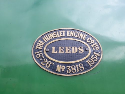
Below – Locomotive 3818 manufactured by The Hunslet Engine Company Limited, founded in 1864 in Hunslet, Leeds, England.

.
Below – The cab of the above locomotive and depicting the open firebox.

Below – The firebox where coal would be shovelled in and burned.

Below – Inside the firebox. The ‘holes’ at the back are the flues or pipes through which the heat will pass and boil the water in the surrounding boiler to create steam.
The fire bricks are made in pairs in order to span the firebox. (Note – SBH – Note the middle join. I don’t think they are cemented together?) On each outward end, the bricks are notched and slide onto a sloping rail attached to the wall of the firebox.
Without a brick arch not only was less heat got from the coal, but considerable smoke was emitted. This had been a concern from the earliest times, and to use an old Victorian expression, locomotives were “required to consume their own smoke”. The initial way to do this was to use coke. A brick arch allowed the use of regular coal, much cheaper as well as more efficient.

Below – The engineers at Bo’ness use a board to note which locomotive requires which size of fire arch. Each size produced is given a different colour so Engine no 7 requires 6 yellow fire bricks and 2 white.

Below – A stack of fire bricks colour coded yellow and red for different sizes. Two metal fire brick mould can also be seen in the foreground.

Below – A stack of fire bricks colour coded yellow and red for different sizes

Below – A stack of used fire brick arches.

Below – Fire brick wedges and mould. These are sometimes used to assist in making sure the fire arches are tightly held within the firebox.

Below – A fire brick arch mould and some newly moulded examples.

Below – A stack of fire brick arches marked in white.

Below- Bags of Ultracast 1400 which are used to produce the fire brick arches. (28/04/2018 – Note – SBH – I am currently trying to confirm the manufacturer and the content of the product)

Below – The next 4 photographs are of a fire brick arch (1 section) kindly donated by the engineers at Bo’ness. It has been used as can be seen by the heat damage to the underside. This is the right-hand side of the arch. There would be a similar brick facing left to complete the arch and there would likely be 3 or 4 sets of these in the firebox.

.

.

.
